Construction
of
ANNA
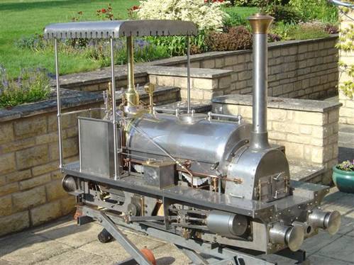
The finished loco awaits painting
Building
The Locomotive
The set of 35 drawings should be the starting point for anyone intent on building the model. Since the prototype was built from them, they were obviously used to prove their accuracy and a policy has been adopted to make any corrections or clarifications as the work proceeded. So it can be confidently claimed that the drawings are error-free in their available state. Most are produced to A2 size, with a few to A3 or even A4 for the finer details. Sets are sent out rolled in a cardboard tube for safe handling
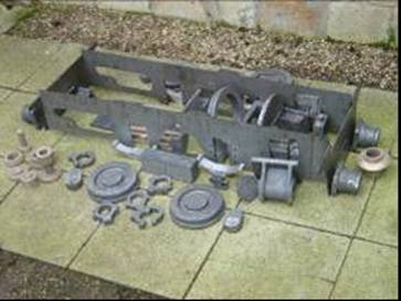
Facilities have been developed to provide strategic materials and back-up advice for all those who wish to build the locomotive. A complete set of castings is available at competitive prices as detailed elsewhere in the website. 31 different patterns are used to produce the whole set of 71 castings and we endeavour to maintain a stock of them; normally deliveries from the foundries can be achieved within three weeks for any shortfalls. An idea of the scale of the operation can be gleaned from the photograph of the array of patterns and castings in store in the builder’s premises, with the addition of some of the other components alongside
Inevitably there will be problems from time to time with casting qualities; a policy of replacement without quibbling is honoured and mercifully the incidence of problems is small to date.
Laser Cut
Componants
Some 200 pieces are available, made up in sets, to ease the problems of sourcing the major materials and to remove the drudgery from some of the preparation work, at the same time ensuring accuracy of the build.
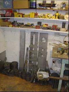
Some examples of these are worth examining in detail: the main frames, which contain slightly different drilling patterns, normally have all the cut-outs and larger holes finished, with the small rivet holes laser spotted. These are easily opened up with a small drill, the recommendation being for drills to be 4-facet sharpened, so that their points have no difficulty in following the hole positions accurately. The small holes line up with corresponding ones in angle iron pieces, which in turn are drilled to positions defined on the drawings, matching with holes in the running boards or footplate sections. A sample of these can be seen just to the left of the main frames in Photo 1. These sets of footplate parts consist of seven pieces and include not only the main and subsidiary footplates, but also the rear footsteps beneath the cab.
Other laser cut components include the valvegear parts, main brake components, cylinder drain cock levers and connecting and coupling rods complete with cotters. Even the boiler and cylinder cladding panels and the cabsides with the sand boxes are available, but pride of place should go to the saddle tank set, canopy and tender kit.
In these sets, the principal components are tabbed and slotted in such a way that, after rolling or bending the pieces may be accurately positioned ready for welding or silver soldering into final form. In fact the tender kit has been likened to an MFI kit, only stronger! There is no doubt that this method of preparation saves a whole lot of time during construction, so much so that in the initial build of the prototype I had the joints made and welded within two days of starting out. This included rolling the top trim pieces and separating them from their matching partners, as well as rolling up the tank filler parts which are then welded into position.
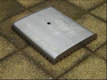
The canopy is supplied as three pieces, namely the two ends and the top. The latter must be rolled to the two radii shewn on the drawing; this leaves a series of tabs sticking out from the two end edges, which fit into slots in the canopy ends. After welding, the excess material is ground off from the end panels. The two pictures are self explanatory.
Other Techniques And Materials
The expansion links and die blocks are available as wire-cut profiles, this process producing results so accurate that lapping the components together produces a perfect result in less than an hour. The material here is 3/8 in. thick gauge plate, which is left unhardened. Economical production has to be achieved by manufacturing the sets four pairs at a time.
Brass bezels to fit around the front and back of the firebox are spun from the correct brass and supplied with sufficient offcut material to provide for the vertical legs of the finished bezels, making for joints which cannot be seen after silver soldering and polishing, with no change in colour across the joints.
On the original model extensive use has been made of stainless steel, virtually all the parts which are left unpainted being machined from this material; clearly this is a matter of personal preference in any construction and guidance on the subject is given in the drawings and articles. It is not pretended that Anna is a simple model to build, although the materials available ease the task considerably.
Just as quarry Hunslets over the
years have become commonplace at many of the tracks and exhibitions the length
and breadth of the land, so it is hoped that the Manning Wardle will take its
place alongside them and add to the variety and interest of the miniature
locomotive fleet. Although designed in 7
¼ in. gauge for British and European running, the necessary variations for 7 ½
in. gauge in the