The
Importance of
ANNA’s
Design
The
1860’s decade saw a major expansion of locomotive-worked narrow gauge railway
networks both at home and abroad but in the field of locomotive design for
railways of 2ft. 6in. (760 mm) and under, locomotive design was far from
settled. The 18 inch gauge lines in use at Crewe works had seen the
introduction of a design of four-wheeled locomotive with inside cylinders and a
cylindrical firebox that was destined to have but a few direct descendants
elsewhere, whilst the Festiniog and Festiniog & Blaenau Railways, both nominal 2ft. gauge,
again employed locomotives with mainframes placed between the wheels and which,
owing to their firebox dimensions, were not continuous throughout the full
length of the locomotive. At the end of the decade, the Festiniog
made another leap forward with the first of its articulated ‘Fairlies’ Little
Wonder but this was yet another specialised design only suitable for
applications that demanded an articulated locomotive. The simple mechanical
solution to the problem of providing a true locomotive type firebox with
continuous frames on such a small gauge was to place the mainframes outside the
wheels but by 1869 there had only been one well-known builder who had
publicised such designs in the domestic professional media. This was Isaac Watt
Boulton of Ashton-Under-Lyne who had constructed at
least two such locomotives in the early part of the decade, but these had yet
another peculiarity in that they were geared, a complication that was unlikely
to appeal to the mass market.
At
this stage of the discussion, it should be noted that in order for full
advantage to be taken of the room provided by the use of outside frames, the
firebox width should not be constrained by the locomotive’s wheelset
‘back-to-back’ dimension. Translated into layman’s terms for a simple 0-4-0
tank locomotive this means that from a side elevation point of view, the arc if
the rear coupled wheels should not foul the firebox. The Boulton
locomotives actually passed this test but two designs used in
The
city of
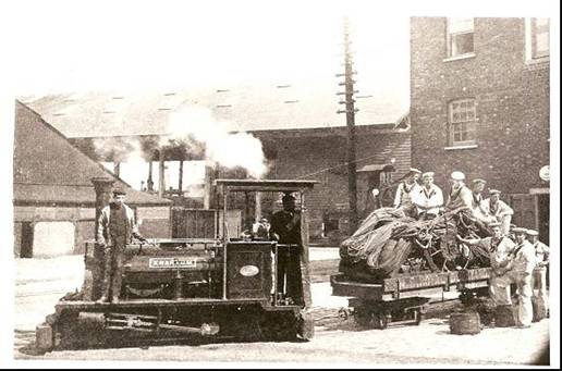
Picture
1
Although
this locomotive and a duplicate supplied seven years later achieved respectable
working lives, their rather clumsy design and 4ft. 3in. coupled wheelbase were not
suited to many industrial applications and it did not achieve the distinction
of large scale series production. In the following year the Royal Arsenal,
which was in the process of adopting the 18 inch gauge used at Crewe Works,
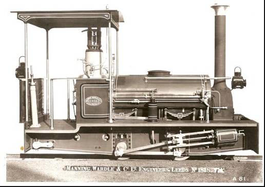
purchased Lord Raglan (works number
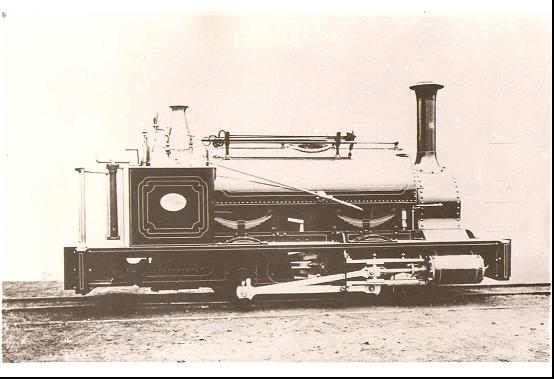
353) from Manning Wardle and this locomotive is illustrated in Picture 2.
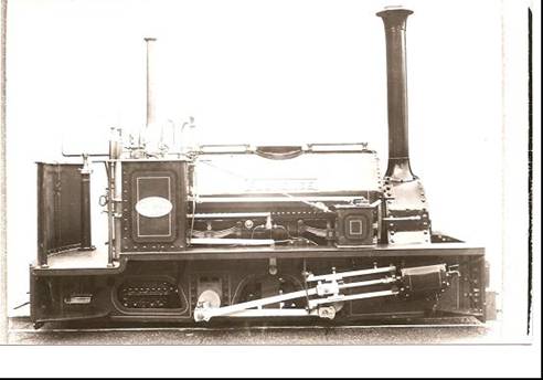
Picture 2
Its
leading dimensions were: Wheels 6in. bore and 8 in. stroke; wheels 1ft. 8 in.
diameter; wheelbase 3ft. 3in.; weight approximately six tons. When new, the
locomotive was fitted with rather ungainly bufferbeams
capable of handling standard gauge wagons as the discrete 18 inch gauge ‘plateway’ track had yet to be laid, but as this expanded
and more locomotives arrived, the standard ‘Woolwich’ variant evolved with
chamfered mainframes, bevel geared handbrake (attached to firebox wrapper),
narrower running boards and ‘composite’ buffers. This is illustrated in Picture
3 by works numbers 613 of 1876 and 1130 of 1889, the latter the last of the
13-strong ‘Woolwich’ contingent to be supplied.
Picture 3
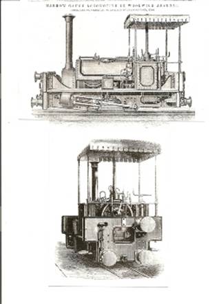
Chatham
Dockyard installed another 18 inch gauge system and again in 1871 purchased Trafalgar (works number 386) from
Manning Wardle. This locomotive was generally similar to Lord Raglan, possessing the latter’s relatively long front and rear
overhangs, wide running boards and (probably) standard gauge-pattern bufferbeam, but this would not have been extended upwards
to handle standard gauge wagons. Within one year, the basic design had been
refined by reducing overhangs and footplate width (the latter measure was to
allow two locomotives to pass one another) and by simplifying the bufferbeam design, although at this stage standard gauge
pattern buffers were retained (Picture 4).
Picture 4
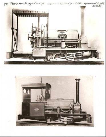
Although
only the last two of the Dockyard’s six members of the basic specification
would have been identical as supplied, common features of the last four at
least would have been rectangular mainframes with rear ‘drop’, Lord Raglan-pattern handbrake; simple
plate bufferbeams, and composite buffer. One of the
final pair is illustrated in Picture 5.
Picture 5
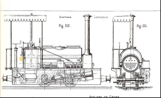
Whilst one further 18 inch class member (similar to
424 of 1872 Busy Bee for the Dockyard
as illustrated in Picture 4) was supplied to the School of Military Engineering
at Chattenden in 1873, four wider gauge examples (designated
the ‘Locke’ class) were constructed
between 1874 and 1878, the first two for home use (Pictures 6 and 7) and the
later two for India.
Picture 6
Picture 7
There was also one 18 inch gauge example for
Picture 8
As a result of the introduction of a basic locomotive
specification that was built over 53 years, the simple outside framed narrow
gauge locomotive was now firmly ‘on the map’ as a commercially viable product.
The most immediately apparent development (from 1879 onwards) was the
mainstream ‘Quarry Hunslet’ locomotive group, but
many celebrated narrow gauge locomotive designs at home and abroad owed their
existence to the appearance of Lord
Raglan and Busy Bee in The Engineer, Engineering and the Vignes Etude of the 1870s. These include Hunslet 0-6-4ST Beddegelert and 2-6-2T Russell; the Manning Wardle 2-6-2Ts for the Lynton
& Barnstaple Railway and 2-6-4Ts for South Africa; the Vale of Rheidol Railway 2-6-2Ts; the 2-6-4Ts for the Leek &
Manifold Light Railway (and related designs for India’s Barsi
Light Railway); tank locomotives of both 0-4-0 and 0-4-2 configurations by
several builders used an the Royal Arsenal; enlarged 0-4-0STs at Chatham
Dockyard, the Kerr, Stuart 0-4-2STs and 0-6-2T used on the Sittingbourne & Kemsley Railway (and their classmates for export), and
various designs used on the Chattenden & Upnor Railway, all to name but a few! A selection of
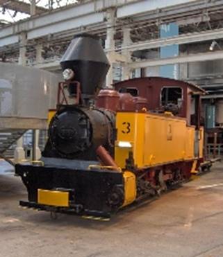
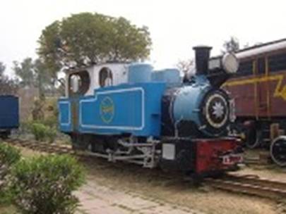
‘descendant’ locomotive designs are illustrated in Pictures 9-15 and these
include not only British-built examples for home use, but also examples for
export, an Australian-built specimen and two German-built representatives
fitted with sleeved axle articulation.
Picture 9 (‘Irish Mail’)
Picture 10 (2ft gauge Perry 0-6-2T ‘Flash’)
Picture 11 (Chattenden & Upnor Railway 0-6-2T ‘Chevalier’)
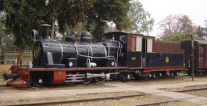
Picture 12 (Matheran Railway
0-6-0T No 739)
Picture 13 (Durley Light
Railway 0-8-0T)
Picture 14 (Bengal
Picture 15 (Hunslet Engine Co
Ltd No 3902)
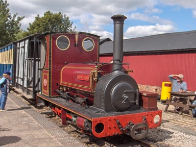
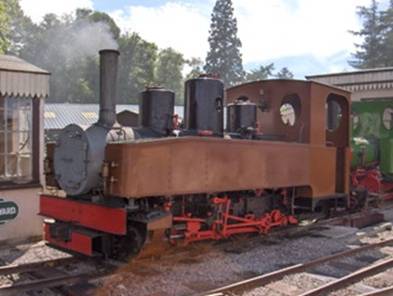
Anna is closely based on the second of the Chatham
Dockyard locomotives, Busy Bee, but
the mainframe shape has been modified on the lines of Lord Raglan to facilitate loading onto and off the running track.
The gauge of 7 ¼ in. also scales at slightly more than the prototype,
approximating to a full size (at 3/8 scale) of just over 19 inches.
For further discussion of the relevant phase in narrow
gauge locomotive evolution generally, see M. Smithers
An Illustrated History of 18 Inch Gauge
Steam Railways (Haynes/OPC 1993).
An Unexpected Spin Off To Anna’s Design
The sphere of 18 inch gauge railways, which Manning
Wardle did so much to advance in the few years following 1871 was to grant the
Leeds company an unforeseen place in history a quarter of a century later. The
Royal Arsenal had seen experimentation in the early 1880s with compressed air
as a safer alternative to steam motive power in an explosives environment. On
its standard gauge network, a locomotive using this mode of power and supplied
by Manning Wardle in 1880 (Maker’s Number 761) saw service in 1880-1 although
it is likely that its reservoir and possibly its two triple expansion three
cylinder engines were supplied by another maker. The late nineteenth century
also saw experimentation with the internal combustion oil engine as a source of
stationary and motive power and some of the most successful outcomes of this
work were the patents of Yorkshireman Herbert Ackroyd Stuart (1864-1927) which
resulted in a pioneering heavy oil compression ignition four stroke oil engine
that anticipated the later work of Dr. Rudolf Diesel (1858-1913). The
manufacturing rights to this engine were bought out in 1891 by the Grantham
concern Richard Hornsby & Sons (later to become part of Ruston Hornsby
& Co. Ltd) who produced progressively improved variants of the engine in
large numbers and sought previously untried applications for it. The year 1896
saw a 20HP variant employed in a road tractor, at least two examples of which
survive today, whilst the 23rd July of that year saw delivery of a 9 ½ HP 18
inch gauge railway locomotive to the Royal Arsenal. The single cylinder ‘hot
bulb’ engine was 11 in. bore by 15 in. stroke whilst the transmission
incorporated a bevel gear reverse train (actuated by a dog clutch), two speed
spur gearing and a final jackshaft drive onto a chassis which, apart from its
inclined horncheeks (in order to relieve suspension
stress on the jackshaft rod), owed much to contemporary 18 inch gauge steam
locomotive practice.
The design of the chassis posed one essential
question, namely did Hornsbys, who had no experience
of producing railway locomotives at this
stage, build it ‘in house’ or did they turn to a more experienced maker to
supply it and merely fit their own engine and transmission gearing assembly? In
order to answer this question, three further illustrations and a crucial piece
of recently discovered documentary evidence are necessary. Firstly, it is
necessary to closely examine the works photograph of the locomotive (Hornsby 1705
of 1896) and its counterpart engraving for the professional journals of the
period, respectively Pictures 16 and 17.
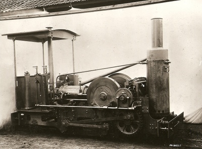
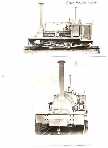
Picture 16 (R. Hornsby No 1705 of 1896 Works Photograph)
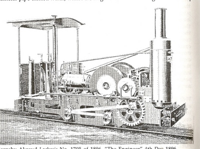
Picture 17 (R. Hornsby No. 1705 of 1896 Engraving)
The design of canopy is noteworthy, being very similar
to the one used on the three 18 inch gauge Manning Wardles
of 1890-1924 for
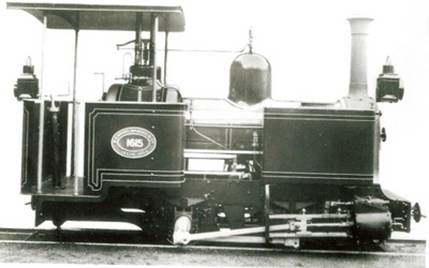
Picture 18 (2ft. 6in. gauge Manning Wardle 0-4-0T No.1615
of 1903 based on No.1322 of 1896)
All of the obvious similarities, together with the
fact that the coupled wheel diameter on the Hornsby was the same (1ft. 8 in.)
as for the 1871 18 inch gauge Manning Wardle, and the fact that No. 1615’s
eldest sister 1322 dated from the same year as the Hornsby led only to one
conclusion, namely that Manning Wardle supplied a ‘rolling chassis’ complete
with canopy to Hornsby in 1896 for use on the new locomotive. Until recently,
there was no documentary evidence to back this assertion up as the relevant
Manning Wardle records do not survive, but a recent project to conserve the
surviving Hornsby records has supplied the missing piece of the jigsaw. Drawing
No. 14453a, which covers the wheels, axles, springs, coupling and transmission
rods is clearly marked with the legend ‘These details were bought from Messrs.
Manning Wardle & Co.’. It therefore seems certain that the work of Manning
Wardle in the 1870s that resulted in the mainstream narrow gauge steam
locomotive becoming a commercially viable proposition also had one unforeseen
spin-off, namely the world’s first commercially viable internal combustion
locomotive. This achievement should now be universally recognised by railway
historians everywhere. In the event, four further locomotives working on the
same principle were supplied by Hornsbys to the
Arsenal at Woolwich between 1900 and 1904, whilst the pioneering engine and two
others survived to be sold to a Darlington dealer in 1919. In the event,
Hornsby No. 1705 was last heard of at the same location ten years later but
rumours persist that it survives somewhere in North Wales!